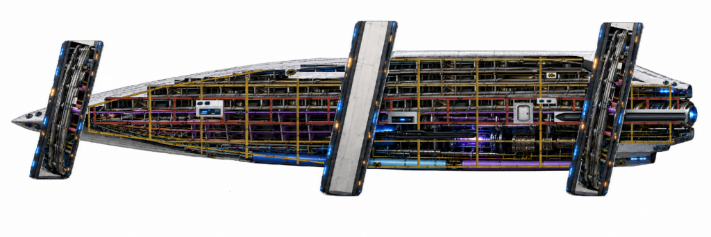
Between the crew and the void sits a multi-hull structure that absorbs radiation, deflects high-velocity particles, and isolates damage. This chapter describes the architecture, the water shield system, and the automated response when something gets through.
Hull Architecture
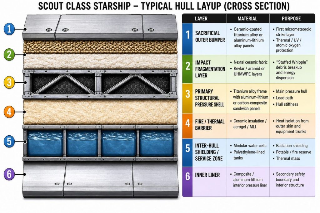
The Scout Class uses a multiple hull architecture. It is comprised of a titanium-alloy spaceframe and pressure shell, covered by replaceable ceramic-coated aluminum-lithium/titanium sacrificial armor panels. It is backed by a stuffed Whipple shield of Nextel ceramic fabric and Kevlar/UHMWPE, with modular water shielding behind it in the inter-hull zone.
Water shielding
Because water is mainly hydrogen it is incorporated in the Inter-Hull as a shield because it is effective against particle radiation. It also doubles as:
- potable water reserve
- fire reserve
- thermal mass
- emergency radiation storm shelter shielding
- ballast/mass distribution system
Water is stored in Distributed water ballast cells in the fifth layer of the hull. However, water is not distributed uniformly across this entire layer of hull volume. Modular water cells are concentrated more heavily around high-occupancy areas.
Hull Water Cells
The Hull Water Cells provide radiation protection using hydrogen-rich water stored within the inter-hull space. They provide primary protection against:
- Galactic cosmic rays
- Solar particle events
- Secondary neutron radiation
while also providing
- Thermal mass
- Emergency reserve
- Ballast and trim control
Hull Water cells are not distributed uniformly. There is a higher concentration around:
- Crew cabins
- Command deck
- Medical bay
- Mess hall
With a reduced concentration around cargo spaces and machinery spaces like around engines, radiators, reactor spaces, and high-heat equipment trunks.
| Category | Region | Inter-Hull gap |
|---|---|---|
| Bow Cells | Command Deck | 1.5–2.0 m |
| Mid-body Cells | Cabins Mess / lounge Medical / Storm Shelter | 1.5–2.5 m 1.5–2.0 m Surrounded by 4 m water shielding on all sides. |
| Engineering Cells | Engineering | 0.75–1.5 m |
| Stern Cells | Propulsion | 0.5 m |
Including storing potable water, the inter-hull space is used to house and route the following systems:
- graywater routing
- potable water manifolds
- coolant loops
- power conduits
- fiber/data trunks
- air return ducts
- environmental sensors
- micrometeoroid breach sensors
- hull patching hardware
Each modular water cell contains leak detection, pressure, and radiation sensors, isolation valves, and drain/fill capability.
Reference Shielding Water System section for additional information.
Structural Support
The Scout Class uses a load-bearing internal structural architecture rather than relying on the pressure hull as the primary strength member. A reinforced central keel spine runs longitudinally through the vessel and carries main bending loads, propulsion thrust, reactor mass, cryogenic tank loads, and deck-frame attachments. A dorsal backbone carries upper warp-ring pylon loads, radiator housing, armored power conduits, and thermal manifolds.
Transverse ring frames spaced along the hull maintain the lifting-body shape and transfer loads between the outer hull, pressure hull, decks, keel spine, and dorsal backbone. Heavy pylon root frames are installed at each warp-ring station to spread mechanical, thermal, and electromagnetic loads from the ring pylons into the primary structure.
The stern propulsion block is attached to a dedicated aft thrust frame that transfers engine loads directly into the central keel spine. Reactors, cryogenic tanks, capacitor banks, and major equipment are mounted in isolated cradle frames to control vibration, magnetic loads, and thermal expansion. Habitable decks are secondary framed platforms suspended within the pressure volume and are not primary structural members.
A distributed structural health monitoring system continuously tracks strain, vibration, thermal expansion, pylon alignment, hull stress, and crack propagation. The ship’s AI uses this data to update the digital twin, predict fatigue, recommend maintenance, and restrict unsafe warp, propulsion, or maneuvering operations.
At 160 m long, 55 m hull beam, 78 m warp-ring beam, and ~40,000 t loaded mass, the ship does not rely on a pressure hull alone. While the pressure hull contains atmosphere; the internal truss/backbone carries major loads. Components include:
| Structure | Function |
|---|---|
| Central keel spine | Main longitudinal strength member |
| Dorsal backbone | Carries upper pylon and radiator loads |
| Transverse ring frames | Maintain hull shape and distribute loads |
| Deck support frames | Carry internal deck loads |
| Pylon root frames | Transfer warp ring loads into the hull |
| Aft thrust frame | Carries sublight engine thrust into the spine |
| Reactor cradle frames | Isolate reactor mass and vibration |
| Pressure hull | Contains atmosphere; not primary bending structure |
The ship uses a distributed structural health monitoring network embedded in the keel, pylon roots, ring frames, thrust frame, and pressure hull. The system tracks strain, vibration, thermal expansion, fatigue, crack propagation, and pylon alignment.
Hull Penetration Response (HPRS)
The overall objective of the Hull Penetration Response system is to preserve life, maintain pressure integrity, protect critical systems, and prevent localized damage from becoming a vessel-wide casualty.
The Scout Class employs a layered hull architecture designed to detect, isolate, and mitigate hull penetrations while preserving crew safety and vessel survivability. The vessel’s multiple-hull construction provides several opportunities to stop, contain, and repair damage before a breach reaches occupied spaces.
Penetration Classification
Hull penetrations are classified into four categories:
| Category I Outer Hull Damage | Damage limited to sacrificial armor panels, micrometeoroid shielding, or external structures. |
|---|---|
| Category II Inter-Hull Penetration | Damage extending into the inter-hull zone affects water-shielding cells, conduits, coolant loops, or service trunks without compromising the pressure hull. |
| Category III Pressure Hull Breach | Damage penetrating the habitable pressure boundary resulting in atmosphere loss or compartment depressurization. |
| Category IV Structural Penetration | Damage affecting primary load-bearing members including the keel spine, pylon root frames, ring frames, dorsal backbone, or thrust frame. |
Detection
Hull penetrations are detected through multiple independent systems including:
- Impact sensors
- Acoustic emission detectors
- Hull strain gauges
- Pressure sensors
- Leak detectors
- Water-cell monitoring sensors
- Thermal imaging sensors
- Structural health monitoring systems
Sensor information is continuously analyzed by the ship’s AI to determine penetration location, severity, probable cause, and expected failure progression.
Response Sequence
| Stage 1 Detection | Upon detection, the affected compartment or hull segment is automatically identified. The ship determines whether the penetration involves: Outer hull • Water shielding cells • Inter-hull services • Pressure hull • Structural members |
| Stage 2 Isolation | Affected systems are isolated automatically. Actions may include: • Closure of watertight isolation valves • Shutdown of damaged coolant loops • Isolation of power trunks • Rerouting of data networks • Activation of compartment pressure doors • ECLSS zone isolation |
| Stage 3 Stabilization | The ship attempts to preserve habitability and prevent damage propagation. Actions may include: • Atmosphere redistribution • Emergency oxygen injection • Water-cell isolation • Automatic ballast correction • Power rerouting • Thermal loop bypass activation |
| Stage 4 Damage Assessment | Inspection drones are dispatched to determine: • Extent of physical damage • Structural integrity • Leak rates • Radiation exposure • Repair requirements Results are displayed on engineering and damage-control consoles. |
| Stage 5 Repair | Temporary repairs may include: • Automated hull patch deployment • Sealant cartridge application • Pressure curtain installation • Structural bracing • Manual crew repair teams Permanent repairs are normally performed during maintenance cycles. |
Water Shield Cell Flooding
If a penetration ruptures one or more shielding-water cells, the affected cells are automatically isolated using local shutoff valves.
The Fluid Management System (FMS) evaluates:
- Water loss
- Ballast effects
- Radiation shielding degradation
- Center-of-gravity impact
Remaining water cells are rebalanced as necessary to maintain vessel trim and shielding effectiveness.
Pressure Hull Breach Response
When a pressure hull breach is detected:
- Pressure doors automatically close.
- Ventilation is isolated.
- Atmosphere loss is minimized.
- Emergency lighting activates.
- Crew accountability procedures begin.
- Repair drones and damage-control teams are dispatched.
Compartment pressure may be reduced gradually in adjacent spaces if required to reduce structural loading.
Structural Penetration Response
If primary structural members are affected, the Structural Health Monitoring System continuously evaluates:
- Load redistribution
- Fatigue growth
- Crack propagation
- Warp-ring alignment
- Thrust-frame integrity
The ship may automatically impose operational restrictions including:
- Warp lockout
- Sublight acceleration limits
- Maneuver restrictions
- Compartment access restrictions
Crew Notification
Because the Scout Class is designed for operation by civilian crews, emergency information is presented using simplified status indicators. The AI provides clear instructions and recommended actions while damage-control personnel coordinate recovery operations.
| Green | No penetration detected |
| Yellow | Minor hull damage |
| Orange | Pressure or service-system damage |
| Red | Major structural or pressure-hull breach |
High-Velocity Particle Protection System (HVPPS)
During warp the ship is enclosed within a warp bubble. The vessel is not moving through local space in the conventional sense. Instead, space contracts ahead and then behind. The ship remains locally stationary inside the bubble. Because of this Interstellar dust is not striking the hull at warp velocity, gas atoms are not impacting the hull at warp velocity, and micrometeoroids are not impacting the hull at warp velocity. The warp field itself becomes the primary protective mechanism. Therefore, a traditional forward shield is generally unnecessary while the warp field is fully established. The primary concern becomes what is encountered when the bubble collapses.
For high velocity sublight flight, the Scout Class employs a multi-layer protection architecture. The system combines long-range hazard detection, autonomous collision avoidance, electromagnetic particle deflection, plasma stand-off shielding, and physical Whipple-style hull protection to mitigate impacts from dust, micrometeoroids, and charged particles.
The system is intended to reduce risk during sublight operations and is not designed to withstand direct collisions with large bodies. Navigation avoidance remains the primary method of collision protection.
Through the forward sensor array when the ship detects any form of debris it notifies the Navigation System to adjust course as a primary defense. However, the vessel also has other particle defense features.
| Electormagnetic Deflection Field | Charged particles are diverted around the ship | Useful against: Solor wind Plasma Ionized duct Cosmic particles |
| Plasma Stand-Off Field | A low-density plasma projected ahead of the ship. | Benefits: Vaporizes tiny particles. Reduces impact energy. Creates a buffer region. |
| Whipple Shielding | Physical protection. | Consists of: Outer sacrificial hull Water shielding layer Pressure hull |