Power, life support, sensors, communications, damage control, and everything else that makes the ship more than a hull. This is the longest chapter — use the on-page navigation to jump to a specific system.
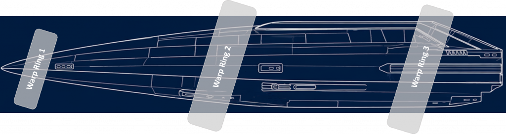
Introduction
The Scout Class starship is built around an integrated systems architecture that allows the vessel to operate as a self-contained exploration platform. Each major ship system supports a specific operational requirement — power generation, propulsion, life support, environmental control, navigation, communications, thermal management, fluid handling, damage control, crew safety, and mission operations — but none of these systems operates in isolation. They are designed to function as a coordinated whole under the supervision of S.C.O.U.T., the ship’s integrated operating and supervisory intelligence.
The purpose of this section is to define the major ship systems that allow the Scout Class to function as a credible long-duration exploration vessel. These systems provide the infrastructure behind the crew experience: breathable air, potable water, artificial gravity, power distribution, reactor control, thermal stability, propulsion support, sensor operation, internal communications, waste handling, emergency response, and routine maintenance. Together, they form the operational backbone of the vessel.
The Scout Class uses a layered approach to system design. Primary systems provide normal mission capability. Redundant pathways preserve essential function after equipment failure or localized damage. Emergency systems provide a survivable fallback when primary and secondary systems are degraded. Critical systems are separated where practical, locally controlled where necessary, and protected by physical interlocks that prevent unsafe operation regardless of software state.
System integration is managed through S.C.O.U.T. and the ship’s hardened command-and-control network. The AI continuously monitors system status, identifies emerging faults, recommends corrective action, optimizes power and thermal loads, and routes alerts to the appropriate crew stations. Engineering consoles provide detailed control over power, thermal, reactor, life-support, fluid, and maintenance systems, while other role consoles receive system information relevant to their duties. For example, the Pilot sees propulsion and inertial-compensation status, the Navigator sees navigational sensor confidence and course constraints, and the Science station sees sensor allocation and data-system capacity.
Although the Scout Class is an advanced starship, its systems are intentionally designed to remain understandable and operable by a small crew. Normal operations are automated where appropriate, but human authorization remains required for mission-critical actions such as reactor mode changes, warp initiation, major propulsion events, section venting, emergency load shedding, and damage-control overrides. Automation assists the crew; it does not replace command responsibility.
For the Starship Adventures implementation, these systems also serve an important experiential function. They give the vessel internal logic. Guests and crew are not simply moving through themed rooms; they are living inside a believable machine with power buses, atmosphere zones, water reserves, pressure compartments, fuel systems, sensor arrays, maintenance corridors, and emergency procedures. The more consistently these systems are defined, the more convincing the ship becomes as both a fictional spacecraft and a full-scale immersive simulator.
The following sections define each major system, its purpose, physical location, operating logic, redundancy model, crew interface, failure behavior, and relationship to other ship systems. Collectively, they describe how the Scout Class sustains life, moves through space, manages risk, supports mission operations, and remains operational during both routine exploration and simulated emergency conditions.
Inertial Management System (IMS)
The Scout Class employs an Inertial Management System (IMS) integrated with the Artificial Gravity System. During sublight maneuvering the IMS moderates acceleration forces experienced by the crew by reducing, distributing, and smoothing inertial loads throughout the vessel. Rather than eliminating all acceleration effects, the system maintains perceptible motion cues to preserve crew situational awareness while preventing harmful acceleration levels. During routine propulsion operations personnel may experience mild acceleration sensations corresponding to ship maneuvering. During emergency maneuvers the IMS automatically increases compensation levels to maintain crew safety and operational effectiveness.
During warp the ship is not accelerating through space in the conventional sense. The warp field is moving spacetime around the vessel, so the crew does not experience acceleration forces. Therefore, no inertial compensation is required during steady-state warp. The only times the IMS might be required are during warp entry, warp exit, warp field instability, and emergency warp shutdown
When sublight propulsion is engaged the inertial management system only removes dangerous forces. For example, if actual acceleration is 0.5 g, the Inertial compensation removes 0.4 g so the crew only experiences 0.1 g. This still produces a noticeable sensation.
The IMS is integrated with the Artificial Gravity System.
Artificial Gravity System (AGS)
The Scout Class employs an Artificial Gravity System (AGS) integrated into its deck plates on every habitable deck. Distributed gravitic projectors embedded beneath deck structures generate a controlled downward acceleration field equivalent to standard Earth gravity. The field is projected approximately 3 meters above the deck and is continuously shaped by local gravity controllers. Adjacent deck fields overlap to produce a uniform gravity environment throughout occupied compartments. The system is compartmentalized by deck and pressure zone, allowing localized operation, maintenance, and casualty isolation.
Gravity levels may be adjusted between 0.2 and 1.2 g for operational, medical, or training purposes. Under normal conditions the AGS provides a continuous 1.0 g environment throughout all occupied spaces. The system is integrated with the ship’s inertial management architecture to minimize perceived acceleration during maneuvering and warp-field transitions.
Deck Plate Components:
- Gravitic Projectors
- Local Gravity Controllers
Field Characteristics (Normal operation):
| Parameter | Value |
|---|---|
| Nominal Gravity | 1.0 g |
| Minimum | 0.2 g |
| Maximum | 1.2 g |
| Field Uniformity | ±2% |
| Response Time | <1 sec |
Localized Generation
Each deck contains:
- primary gravity grid
- secondary gravity grid
- emergency gravity grid
This redundancy increases damage tolerance and compartment isolation. If Deck 3 loses gravity Decks 1,2,4,5,6 continue operating.
Gravity Status Indicator Network (GSIN)
Every deck plate has an integrated local Gravity Status Indicator. Indicators provide immediate visual confirmation of local gravity field condition and are visible without requiring access to engineering consoles. Indicators automatically illuminate during gravity transitions, maintenance activities, casualty conditions, and emergency operating modes. The system is intended to provide intuitive status awareness for civilian crews with minimal training while supporting rapid diagnosis by engineering personnel.
Status Colors
| Color | Status | Meaning |
|---|---|---|
| Green | Normal | Gravity field within nominal limits |
| Yellow | Reduced | Below established threshold |
| Magenta | Elevated | Above established threshold |
| Red | Failure | Gravity unavailable |
| Blue | Maintenance | Local field disabled intentionally |
| Flashing Red | Emergency | Rapid gravity fluctuation detected |
Failure Modes
| Partial Failure | When gravity decreases: 1.0 g → 0.8 g → 0.5 g crew members notice lighter footsteps, objects easier to lift, and liquids behave strangely. |
|---|---|
| Complete Failure | The deck enters Microgravity Mode |
Power Systems
Power Generation (FRC)
The Scout Class Starship has twin compact FRC Direct Fusion Drive Reactors using Deuterium-Hellium-2 (D-He3) for fuel. The reactors produce high-energy charged particles that are converted directly into electricity with high efficiency while the magnetic nozzle provides thrust for sublight propulsion.
A Brayton Power Cycle is used for thermal recovery converting remaining waste heat into additional electricity. The primary reactor provides main propulsion, warp-field power, ship power. The secondary reactor provides redundancy, hotel loads, emergency propulsion, reactor restart support.
FRC Specifications
| Thermal Fusion Power | 1 to 5 GW / core |
|---|---|
| Electrical Output (DEC) | 0.75 =3+ GW |
| Efficiency (Direct Conversion) | 75-90%+ |
| Reactor Length | 15 m / core |
| Reactor Diameter | 6 m |
Radiation Shielding/Thermal Conversion
D-He3 reactors are shielded with surrounding blankets to absorb neutron energy, to transfer heat to coolant, and provides radiation shielding. The forward side of the blankets are thicker than the aft side to protect crew areas.
Energy Storage (SMES)
Capacitor banks and SMES (Superconducting Magnetic Energy Storage) smooth power fluctuations.
Warp rings and propulsion systems cannot draw directly from the reactors without buffering. They provide power for the sublight propulsion engines and high-power pulses to the warp rings. Two superconducting magnetic energy storage or high-density capacitor banks are located at Dorsal aft and Ventral aft shoulders behind armors shutters.
Power Distribution (PDS)
Power distribution is managed through the Power Distribution system. Buses distribute power to all ship systems: propulsion, life support, systems, warp rings, and sensors. high-energy warp feeds and main reactor buses in protected service trunks and are distributed away from crew spaces.
The vessel has multiple power buses:
| Bus | Purpose | Voltage class |
|---|---|---|
| Main Propulsion Bus | Sublight engines, maneuvering, high-load systems | Very high-voltage DC backbone |
| Warp Field Bus | Warp-ring power conditioning | High-voltage DC, pulsed |
| Ship Service Bus | Life support, computers, lighting, doors, galley, cabins | Medium-voltage DC |
| Emergency Bus | Triple redundant emergency buses for essential systems only | Isolated DC |
| Battery/Capacitor Bus | Surge loads and reactor transient buffering | High-current DC |
The power distribution system manages power distribution, voltage levels, the UPS architecture, battery systems, load shedding logic, circuit protection, and emergency buses.
Casualty Power Architecture (CPA)
The Scout Class employs a distributed casualty power architecture designed to maintain critical ship functions during equipment failures, structural damage, reactor outages, fire events, hull breaches, and network degradation.
Power distribution is divided into multiple independent buses connected through remotely operated switchgear and local isolation controllers. During normal operations, power is supplied through the Main Propulsion Bus, Warp Field Bus, Ship Service Bus, and Battery/Capacitor Bus. In casualty conditions, affected sections can be isolated while emergency power is automatically rerouted through redundant pathways.
The casualty power system is designed around three principles:
- Isolation of damaged systems
- Preservation of critical functions
- Continued ship control
Casualty Power Priorities
When power availability is reduced, electrical loads are automatically prioritized.
Priority 1 – Life Safety
These systems receive power first:
- Environmental Control and Life Support System (ECLSS)
- Emergency lighting
- Damage-control systems
- Fire suppression systems
- Atmospheric monitoring
- Medical systems
- Emergency communications
- Emergency network controllers
These systems remain powered under all operating conditions.
Priority 2 – Ship Control
These systems receive power after life-safety loads:
- Bridge command systems
- Navigation systems
- Communications systems
- RCS control systems
- Propulsion control systems
- Structural monitoring systems
These systems allow the vessel to remain controllable.
Priority 3 – Mission Essential Systems
These systems remain operational when sufficient power is available:
- Sensors
- Observatory systems
- Science laboratories
- Drone control systems
- Data processing systems
Priority 4 – Hotel Loads
These systems are automatically shed first:
- Recreational systems
- Nonessential displays
- Training systems
- Noncritical cabin services
- Observatory public displays
Automatic Isolation
If damage is detected, local power controllers automatically isolate affected circuits.
Examples include:
- Electrical fire
- Short circuit
- Flooded water-shielding cell
- Hull breach
- Power trunk damage
- Thermal runaway
Affected equipment is disconnected from the network while alternate routes are activated.
Emergency Power Sources
Emergency power is supplied by:
| SMES Units | Superconducting Magnetic Energy Storage systems provide immediate uninterrupted power during transient failures. |
|---|---|
| Capacitor Banks | Provide short-duration high-power support for critical switching events. |
| Emergency Batteries | Support: Emergency lighting Communications Emergency network Local control stations for extended periods following reactor loss. |
Casualty Power Trunks
Dedicated casualty power trunks are physically separated from primary distribution pathways. These trunks supply:
- Damage Control Center
- Bridge
- Engineering Control Room
- Medical Bay
- Emergency communications
- Airlocks
- Emergency lighting
Whenever practical, casualty trunks are routed through different compartments than primary power trunks to reduce common-mode failures.
Local Control Capability
Each major compartment contains:
- Emergency disconnects
- Manual isolation switches
- Emergency lighting controls
- Emergency equipment outlets
This allows operation even if central control is unavailable.
Emergency Power Modes
| Condition Orange | Major subsystem failure. Nonessential loads shed Emergency routing activated |
| Condition Red | Ship-wide emergency. Life-safety loads prioritized Science and comfort loads disconnected |
| Condition Black | Loss of primary command and reactor systems. Only emergency buses remain energized. Powered systems include: ECLSS Emergency lighting Emergency communications Emergency network Damage-control systems Medical systems \ |
The vessel remains survivable while recovery operations are conducted.
Human Factors
Because the Scout Class is designed for operation by civilian crews, casualty power routing is largely automated. The ship’s AI continuously evaluates system status, predicts cascading failures, recommends routing changes, and executes approved power reconfiguration plans. Crew members receive simple status indications such as:
- Green – Normal
- Yellow – Reduced Capability
- Orange – Emergency Routing Active
- Red – Critical Power Condition
This minimizes operator workload during emergencies while preserving manual override capability for engineering personnel.
Integrated Communications & Data Exchange System (ICDES)
The Scout Class Integrated Communications and Data Exchange System (ICDES) is designed around three distinct operational environments:
Local Operations
- Within the ship
- Docked operations
- Surface teams
- Nearby spacecraft
Interplanetary Operations
- Earth–Moon
- Planet-to-planet
- Deep solar system
Interstellar Operations
- Beyond the solar system
- Long-duration autonomous missions
- Store-and-forward communications
Faster-than-light communication technology does not currently exist; therefore Communications are constrained by the speed of light, and mission procedures are designed accordingly.
Communications Architecture
The ICDES consists of:
- Internal Communications Network (ICN)
- External Communications Suite (ECS)
- Fleet Communications Network (TCN)
- Emergency Communications System (EMCS)
- Mission Data Network (MDN)
- Communications Control System (CCS)
- Internal Communications Network
- Provides communications within the vessel.
| Components | Fiber Optic Backbone Dual redundant fiber rings running through all decks. |
| Capabilities | Voice Video Data Sensor traffic Command traffic Entertainment systems |
| Bandwidth | 400 Gbps minimum Expandable to multi-terabit operation |
| System | Purpose | Technology | Coverage |
| Internal Wireless Network | Provides portable communications. | Wi-Fi 7 minimum UWB positioning Encrypted crew communications | Entire habitable volume Cargo areas Airlocks Maintenance spaces |
| Intercom System | Emergency communications. General announcements Damage control Fire alerts Medical emergencies | Hardwired | Operates independently of ship network. |
| External Communications | Primary local communications system. | Local operations: VHF EVA operations: UHF Spacecraft communications: SHF High-bandwidth links: EHF | Voice Video Telemetry Docking data Sensor sharing Range: Thousands to millions of kilometers depending on power and antenna configuration. |
| Laser Communications System | Primary long-range communication system. High-bandwidth transmission Point-to-point communication Deep-space networking | Four optical communication turrets Independent tracking systems Adaptive optics | Omnidirectional Distances 1 AU 10–100 Gbps 10 AU 1–10 Gbps 100 AU 10–100 Mbps Interstellar: Depends on aperture and relay network |
| Mission Communications Network | Used during missions. | Local operations: VHS EVA operations: UHS Spacecraft communications: SHF High-bandwidth links: EHF | Drone Communications Flight control Payload control Video transmission Autonomous mission updates Local Area Space Network Probes EVA suits Auxiliary craft Docking facilities |
| High-Gain Antenna Array | Backup deep-space communications. | Phased-array dish system Electronic beam steering | Low-bandwidth communications Navigation support Emergency signaling |
| Emergency Communications System | Automatically activates when required. | RF Laser Automated repeating bursts | Broadcasts: Ship identity Position Status Crew count Distress classification |
| Ship Transponder Beacon | Automatically activates when required. | RF Laser Automated repeating bursts | Broadcasts: Ship identity Position Status Crew count Distress classification |
| Electronic Warfare Protection | Provides resilience against interference. | Frequency hopping Beamforming Directional transmission Signal authentication Jamming detection |
Mission Data Network
Handles scientific and mission data.
Capabilities
- Sensor aggregation
- Data archiving
- Compression
- Prioritized transmission
Storage
• Multiple petabytes of onboard storage
Transmission Priority:
1. Distress traffic
2. Flight safety
3. Command traffic
4. Navigation data
5. Scientific data
6. Passenger communications
7. Entertainment traffic
Communications Control Center
Primary Station – Located on the bridge.
Functions:
- Communications management
- Traffic routing
- Link monitoring
- Encryption control
Secondary Station – Located within Operations/Engineering.
Capable of assuming full control if bridge systems are lost.
Typical Communications Performance
| Function | Capability |
|---|---|
| Ship-wide Voice | Full coverage |
| Ship-wide Video | Full coverage |
| EVA Communications | 50,000 km |
| Drone Control | 100,000 km |
| Spacecraft Communications | Millions of km |
| Planetary Communications | Entire solar system |
| Deep-Space Communications | Interstellar capable |
| Laser Data Links | Up to 100+ Gbps |
| Emergency Beacon | Multi-year automated operation |
Integration with Navigation System
The communications system directly supports the Integrated Astrogation and Navigation System by receiving:
- Navigation beacon signals
- Pulsar timing updates
- Deep-space network data
- Ephemeris updates
- Traffic control information
- Docking guidance signals
- Scientific observatory data
Casualty Communications Routing (CCR)
The Scout Class employs a distributed communications architecture designed to maintain command and coordination capabilities during emergency conditions. Under normal operations, voice, video, data, sensor, and ship-control traffic are routed through the Primary Communications Networks. In the event of compartment damage, power loss, fire, flooding, hull breach, or network failure, the system automatically transitions affected areas to the Emergency Net.
The CCR system continuously monitors network integrity throughout the vessel. When a damaged cable trunk, network node, relay, or communications processor is detected, communications traffic is automatically rerouted through alternate pathways without requiring crew intervention. Redundant communications trunks are routed through physically separated regions of the hull to minimize the likelihood that a single casualty can disable multiple communication paths.
Communications traffic is prioritized according to operational importance. Emergency alarms, damage-control coordination, medical emergencies, engineering status messages, command directives, and distress communications receive the highest routing priority. Routine administrative traffic, crew communications, and non-essential data transfers may be delayed or suspended to preserve available network capacity.
If primary routing becomes unavailable, local Emergency Communications Nodes connected to the Emergency Net located throughout the ship automatically activate. These hardened units provide voice communications, emergency messaging, compartment status reporting, and direct access to Damage Control Central. Emergency Communications Nodes are powered by independent battery reserves and remain operational even during widespread ship power failures.
Should an entire compartment become isolated, surviving communications paths automatically establish alternate routing through adjacent pressure zones, the Maintenance Net, the Engineering Net, and the Emergency Net. If all wired connections are lost, short-range internal wireless emergency links may be established between surviving Emergency Communications nodes to restore limited connectivity.
During severe casualties, the ship may enter Emergency Communications Mode. In this configuration, available communications resources are dedicated primarily to command, engineering, medical, security, and damage-control operations. Non-essential communications are restricted until normal network integrity is restored.
The objective of Casualty Communications Routing is to ensure that no single failure, compartment casualty, or localized damage event can isolate critical personnel from command authority or emergency response resources.
Information Technology (SCOUT)
See SCOUT System Specification for additional detail.
S.C.O.U.T. (Scout Class Operating Umbrella Technology) is the integrated operating system of the Scout Class starship. S.C.O.U.T. It is not a single device but the umbrella under which the vessel’s crew interfaces, supervisory intelligence, computing core, networks, and operational applications are unified into one coherent system. It is the means by which the crew perceives, commands, and collaborates with the ship.
S.C.O.U.T. is composed of the following principal subsystems, each specified in this document:
- Crew interfaces. The means by which crew interact with the system: the touchscreen consoles, the public audio interface, and the personal audio link (earbuds). The relationship between these is defined in the Crew Interaction Tiers overview in the SCOUT System Specification.
- Supervisory intelligence (the AI). The distributed ship intelligence that monitors, advises, coordinates, and operates alongside the crew across every station.
- Computing core. The quantum-primary computing architecture with a classical emergency core that executes navigation, warp-field, AI inference, and ship-management workloads (See SCOUT System Specification).
- Networks. The hardened, domain-isolated command-and-control network connecting all of the above.
- Applications. The operational software the crew uses to run the ship, from propulsion control to life support to the astronomical suite.
Anything the crew can do by touch at a console, they can do by voice through the AI, and the AI continuously supports the operator through monitoring, recommendation, and delegated autonomy. Every console aboard the vessel is physically identical; all role differentiation is implemented in software.
Sensor Arrays
The Scout Class uses a distributed sensor architecture rather than a single centralized sensor suite. External sensors are arranged around the forward, lateral, dorsal, ventral, aft, and warp-ring sections of the vessel to provide complete coverage for navigation, exploration, collision avoidance, planetary survey, docking, propulsion monitoring, and warp-field control.
Internal sensors are distributed through all pressure compartments, service trunks, water cells, power buses, propulsion spaces, life-support systems, and structural members. These sensors continuously feed the ship’s digital twin, allowing SCOUT to detect faults, predict failures, monitor crew safety, and recommend corrective action.
Sensor placement is based on six requirements:
- Full 360-degree external coverage
- Redundant forward hazard detection
- Dedicated science and exploration sensing
- Continuous structural health monitoring
- Independent environmental monitoring by compartment
- Local sensor survivability after damage
The sensor system remains functional in degraded mode even if any single array, network segment, or compartment is lost.
External Sensor Arrays
| Sensor Array | Location | Purpose | Sensors |
|---|---|---|---|
| Forward Sensor Array | bow forward dorsal/ventral surfaces forward lateral hull shoulders | navigation hazard detection exploration collision avoidance This is the ship’s main “eyes forward” sensor suite. | Radar / lidar Infrared sensors Optical sensors Wide-spectrum imaging detectors Passive scanners Active scanners Navigation star trackers Gravimetric / field sensors Collision avoidance sensors Local proximity sensors |
| Lateral Sensor Arrays | port and starboard hull shoulders along mid-body | side-looking scans docking formation flight drone tracking survey work These arrays allow the ship to scan planets, structures, debris fields, or anomalies without pointing the entire vessel directly at the target. | Optical sensors Infrared sensors Radar / lidar side arrays Passive scanners Communications network scanners Local proximity sensors Drone tracking receivers Radiation detectors Magnetic sensors |
| Dorsal Sensor Array | dorsal | science astrometry long range observation mission specialist work This array is directly tied to the Exploration Operations Center. | Observatory instruments Optical telescope systems Infrared telescope systems Spectrograph systems Radio astronomy receivers Star trackers Gravimetric sensors Anomaly detection sensors Wide-spectrum imaging detectors |
| Ventral Sensor Array | lower hull | planetary survey landing area analysis downward mapping thermal monitoring This is the main array for planetary flyovers and surface surveys. | Terrain/topography mapping lidar Ground-penetrating radar equivalent Optical and infrared imaging Atmospheric analysis sensors Radiation detectors Local proximity sensors Heat rejection monitoring Hull thermal sensors |
| Aft / Propulsion Sensor Array | stern propulsion block engine bay aft dorsal ventral shoulders | propulsion monitoring engine safety thrust control wake analysis This array is less about external sensing and more about ship health. | FRC fusion reactor status sensors Fusion load sensors Energy conversion sensors Brayton thermal level sensors Brayton turbine monitors Power demand sensors Main power bus monitors Propellant system sensors Cryogenic fuel tank sensors RCS thruster status sensors Cooling loop sensors Heat rejection status sensors Radiator capacity sensors Vibration monitors Electrical fault detectors |
| Warp Ring / Pylon Sensor Array | warp rings pylon roots ring frames power-feed trunks coolant-feed trunks | warp field stability ring alignment structural safety field monitoring. This is essential because the warp rings are one of the highest risk systems on the ship. | Warp ring status sensors Warp ring feed monitors Pylon power feed monitors Pylon alignment sensors Warp ring-frame alignment sensors Magnetic sensors Gravimetric / field sensors Field symmetry sensors Cryocooling sensors Structural vibration monitors Hull stress detectors Hull strain gauges Acoustic emission detectors |
Internal Sensor Network
The ship also needs internal sensor arrays by compartment.
| Sensors | Location | Purpose | Sensors |
|---|---|---|---|
| Hull / Structural Sensors | Keel spine dorsal backbone ring frames pressure hull pylon roots, thrust frame | Detect impacts Predict fatigue Monitor structural distortion Support the digital twin | Hull strain gauges Hull stress detectors Hull thermal expansion sensors Hull crack propagation sensors Impact sensors Acoustic emission detectors Vibration monitors Leak detectors |
| Environmental Sensors | Every pressure compartment: cabins corridors airlocks service trunks engineering bay medical space | life support control fire detection atmosphere isolation crew safety | Oxygen monitors Nitrogen monitors CO₂ monitors Humidity sensors Temperature sensors Air pressure sensors Smoke/gas sensors Contaminant sensors |
| Fluid Management Sensors | water cells potable tanks ballast lines pumps valves coolant loops hydrazine tanks | water recycling radiation shielding ballast control fire suppression hydrazine safety | Water analysis sensors Tank level sensors Transfer pump status sensors Isolation valve status sensors Flow meters Air/water pressure detectors CG monitors Propellant sensors |
| Power and Network Sensors | power buses switchgear capacitor banks SMES units network trunks emergency net nodes | Detect faults Reroute power Preserve emergency systems Support damage control | Power bus monitors Battery/capacitor state sensors Electrical fault detectors Emergency reserve monitors Communications network scanners System wear monitors Casualty power routing sensors |
Sensor List
| Accoustic Emmision Detectors | FRC fusion reactor status | Power Demand |
| Active/Passive Scanners | Fusion Load | Propellant systems |
| Air/Water Pressure Detectors | Gravimetric/Field Sensors | Pylon Alignment |
| Anomaly detection | Heat Rejection Status | Pylon power feeds |
| Battery/Capacitor states | Hull Crack Propagation | Radar / Lidar |
| Brayton turbines | Hull Strain Gauges | Radiation Detectors |
| Bryton Thermal Levels | Hull Stress Detectors | Radiator capacity |
| Capacitor Status | Hull Thermal Expansion | RCS Thruster Status |
| CG Monitors | Humidity | System wear |
| CO₂ removal | Impact Sensors | Tank Level Sensors |
| Collision Avoidance | Infiltration Sensors | Targeting Scanners |
| Communications Network Scanners | Infrared Sensors | Temperature |
| Cooling loops | Isolation valve status | Transfer pump status |
| Cooling loops status | Leak Detectors | Vibration Monitors |
| Crew Location | Local Proximity Sensors | Visual and wide spectrum Imaging Detectors |
| Cryogenic fuel tanks | Magnetic Sensors | Warp Ring status |
| Door/Hatch Status | Navigation Star Trackers | Warp Ring-Frame Alignment Sensors |
| Electrical Fault Detectors | Observatory Instruments | Warp-ring feeds |
| Emergency Reserves | Optical Sensers | Waste Processing Monitors |
| Energy Conversion | Oxygen /nitrogen Monitors | Water Analysis |
| Flow Meters | Power buses |
Navigation System (IANS)
The Scout Class is equipped with an Integrated Astrogation and Navigation System designed to operate across local, solar-system, interstellar, and galactic reference frames. The system uses inertial navigation, optical stellar tracking, pulsar timing, gravimetric sensing, radar/lidar ranging, beacon transponders, and catalog-based astrometry to determine ship position, velocity, attitude, route safety, and long-range trajectory uncertainty.
The system maintains separate coordinate models for the ship-local inertial frame, the ecliptic plane, the Earth-equatorial celestial frame, and the galactic coordinate frame. Galactic orientation is referenced to the galactic plane, galactic north pole, and the Sagittarius A* region as the best available marker of the Milky Way center, while recognizing that the exact galactic dynamical center and long-term solar-galactic motion remain model-dependent.
The navigation computer distinguishes observed data from propagated models and displays confidence envelopes for all long-duration routes. For deep-space operations, the system uses stellar catalog matching, pulsar timing, quasar references, and gravimetric cross-checks to prevent overreliance on any single astronomical assumption.
Core Capabilities
The IANS is able to:
- Maintain ship position in multiple reference frames.
- Convert between equatorial, ecliptic, galactic, and ship-local coordinates.
- Track attitude, velocity, acceleration, and jerk.
- Plot interplanetary routes.
- Plot interstellar routes using stellar catalogs.
- Correct long-term drift using stars, pulsars, quasars, and gravimetry.
- Distinguish observed position from modeled galactic motion.
- Flag uncertainty when models exceed reliable measurement.
| System/Function | Purpose | Sensor/Data | Capabilities |
|---|---|---|---|
| Inertial Navigation System | Continuous position, velocity, and attitude propagation when external references are unavailable. | Ring-laser gyroscopes Fiber-optic gyroscopes Quantum accelerometers Redundant inertial measurement units Gravimetric drift correction sensors | Dead-reckoning navigation Attitude hold Maneuver reconstruction Backup navigation during sensor blackout Cross-check against star-tracker updates |
| Stellar Reference System | Correct inertial drift using observed star fields. | Wide-field star trackers Narrow-field precision telescopes UV/visible/infrared optical sensors Stellar parallax and proper-motion processor Gaia-derived onboard stellar catalog | Star-field matching Attitude correction Position refinement near known stars Long-duration drift correction Identification of stellar proper-motion errors |
| Galactic Reference System | Maintain orientation relative to the galactic plane, galactic center vector, and north/south galactic poles. | Galactic coordinate catalog Sagittarius A* radio-source reference Quasar/extragalactic reference catalog Pulsar timing grid Long-baseline radio/navigation receiver Galactic coordinate catalog Sagittarius A* radio-source reference Quasar/extragalactic reference catalog Pulsar timing grid Long-baseline radio/navigation receiver | This is where three frame-transform paramaters are applied |
| Solar-System Navigation Suite | High-precision navigation within the solar system. | Radar Lidar Optical telescopes Infrared telescopes Planetary ephemeris receiver Beacon transponder receiver Radio ranging antenna Doppler velocity measurement system | Planet/moon ranging Asteroid and debris tracking Orbital insertion support Station approach navigation Solar conjunction warning Ephemeris correction Time-of-flight prediction |
| Pulsar Navigation System | Deep-space autonomous positioning independent of local beacons. | X-ray pulsar telescope Radio pulsar receiver Atomic clock bank Pulsar timing processor | Position fixing using millisecond pulsars Backup galactic-scale navigation Long-range inertial correction Independent verification of stellar navigation This is especially useful when galactic center location, stellar drift, or local beacon availability is uncertain. |
| Gravimetric / Mass-Concentration Navigation | Detect large gravitational sources and refine course safety. | Gravity-gradient sensors Compact gravimeters Tidal-force monitors Mass-anomaly detector | Planetary mass detection Large asteroid detection Black hole / neutron star hazard warning Navigation through dust-obscured regions Independent check against optical navigation |
| Hazard & Collision Avoidance System | Protect the ship during sublight and pre-warp operations. | Forward lidar array Phased-array radar IR debris scanner Dust/particle impact detectors Micrometeoroid flux sensors Passive optical tracking cameras | Debris detection Closing-rate calculation RCS avoidance recommendations Shield orientation advisories Safe corridor validation Warp exclusion-zone verification |
| Long-Term Galactic Navigation Capability | Rout planning & autopilot | Star positions Proper motion Parallax Radial velocity Pulsar timing Quasar reference points | Because galactic time scales are enormous, the system can explicitly classify data as: Observed Models Solar orbit around galactic center Solar vertical oscillation through galactic plane Galactic center dynamical estimate Future stellar positions Long-term galactic gravitational perturbations Assumed / Estimated Exact galactic midplane Exact dynamical galactic center Dark matter distribution Long-period vertical oscillation causes |
Fluid Management System (FMS)
The Fluid Management System controls, stores, transfers, monitors, recycles, and safeguards all liquid resources aboard the Scout Class Starship.
Functions include:
- Tank monitoring
- Water transfer control
- Fuel balancing
- Leak detection
- Recycling control
- Pump control
- Emergency isolation
The system continuously monitors:
- Fluid levels
- Pressures
- Temperatures
- Flow rates
- Water quality
- Propellant status
The system’s scope includes:
- Potable water
- Water radiation shielding
- Ballast and trim water
- Grey water
- Black water
- Reactor cooling fluids
- Hydrazine RCS propellant
- Emergency firefighting water
- Medical and laboratory water supplies
The FMS is designed to maximize self-sufficiency, maintain vessel balance, support radiation protection, and minimize crew maintenance requirements.
FMS Architecture
The Scout Class Fluid Management System serves five simultaneous purposes:
- Sustain crew life.
- Provide radiation protection.
- Maintain vessel balance and CG.
- Support thermal management.
- Maximize mission endurance through extensive recycling.
By integrating shielding water, ballast water, emergency reserves, and recycling systems into a unified architecture, the ship achieves long-duration operation while maintaining proper mass distribution and minimizing consumable requirements.
The Fluid Management System is divided into seven major subsystems:
- Potable Water System
- Shielding Water System
- Ballast and Trim System
- Waste Water Recovery System
- Fire Suppression Water System
- Thermal Management Fluid System
- Hydrazine Propellant System
Each subsystem is physically isolated but interconnected through monitored transfer manifolds.
Ballast and Trim System (BTS)
This system uses shielding water as movable ballast. It allows control of:
- Longitudinal CG
- Vertical CG
- Port-starboard balance
Dedicated ballast pumps connect:
| Hull Water Cell | Function |
|---|---|
| Bow Cells | Forward trim correction |
| Midship Cells | Primary balance region |
| Stern Cells | Aft trim correction |
| Port Cells | Lateral balancing |
| Starboard Cells | Lateral balancing |
| Upper Cells | Vertical CG management |
| Lower Cells | Vertical CG management |
Engineering computers continuously calculate vessel CG, fuel mass, water mass, and occupancy loads. The system automatically rebalances when required.
Potable Water System (PWS)
Provides drinking water and domestic water for:
- Crew consumption
- Food preparation
- Medical use
- Hygiene
- Laundry
- Housekeeping6.91.3.1 Capacity
- 40 people
- 90-day autonomous operation
Estimated reserve:
| Category | Volume |
|---|---|
| Daily consumption | 4,000 L/day |
| Mission reserve | 360,000 L |
| Emergency reserve | 40,000 L |
| Total potable allocation | 400,000 L |
Wastewater Recovery System (WWRS)
The Wast Water Recovery System processes grey water (showers, sinks, laundry galley), black water (toilets, medical facilities), and condensate (respiration, perspiration, humidity control systems). The system is rated as recovering up to 80-95% of all water consumed. It is stored in dedicated tanks until processed and returned as potable water stored in the hull. Components include:
- Mechanical filtration
- Activated carbon filtration
- Reverse osmosis
- UV sterilization
- Mineral balancing
The Water Treatment Plant is located on deck 2, the Service deck.
Shielding Water System (SWS)
The Shielding Water System (SWS) Provides radiation protection using hydrogen-rich water stored within the inter-hull space (See Hull Architecture).
| Estimated Shielding Mass | 10,000 metric tons |
| Equivalent volume: | 10,000 m³ |
The Inter-hull water cells consist of:
- Modular tanks
- Isolation valves
- Leak sensors
- Pressure sensors
- Transfer manifolds
Each cell can be independently isolated.
Fire Suppression Water System (FSWS)
The FSWS ensures firefighting capability is always available. It is separate from potable system with a dedicated reserve of 100,000 liters but can be supplemented by Potable and Cooling reserves if needed.
The FSWS feeds:
- Fire mains
- Emergency hoses
- Damage-control lockers
- Automated suppression systems
- Emergency Use
Thermal Management Fluid System (TMFS)
This system is responsible for removing heat from:
- Fusion reactors
- Power conversion systems
- Electronics
- Propulsion systems
- Environmental systems
- Primary Loop
It utilizes high-temperature coolant loops for the reactors, propulsion systems, and secondary loops through intermediate heat-transfer loops to
- Radiators
- Thermal storage systems
- Emergency Cooling
Dedicated reserve tanks provide cooling during:
- Reactor shutdown
- Pump failures
- Radiator faults
Hydrazine Propellant System (HPS)
This system supplies monopropellant to RCS thrusters which is separate from all other fluid systems. It is responsible for ship balance stability, reduced plumbing runs, Improved protection, and fuel distribution and tank arrangement. It includes the Forward RCS network, Midship RCS network, and the Aft RCS network. Cross-feed capability is incorporated in the design.
Components include:
- Pressurized storage tanks
- Isolation valves
- Filters
- Flow meters
- Pressure regulators
- Emergency dump valves
- Safety Features
Hydrazine compartments include:
- Leak detectors
- Ventilation systems
- Fire isolation
- Blast panels
- Remote shutdown capability
Fluid Control is accessible through Engineering credentials from any console and include the following functions:
- Tank monitoring
- Water transfer control
- Fuel balancing
- Leak detection
- Recycling control
- Pump control
- Emergency isolation
The HPS continuously monitors:
- Fluid levels
- Pressures
- Temperatures
- Flow rates
- Water quality
- Propellant status
Life Support (ECLSS)
The ship employs a distributed regenerative Environmental Control and Life Support System using closed-loop atmospheric recycling, water recovery, oxygen electrolysis, regenerative CO₂ scrubbing, distributed thermal management, and compartmentalized pressure control. Multiple atmospheric zones can operate independently during damage events, while AI-assisted monitoring continuously manages air composition, temperature, humidity, contaminants, and emergency survivability.
Atmospheric Management System
The ship’s atmosphere is maintained at a “standard atmosphere” both in terms of pressure and composition.
The Atmospheric Management System consists of three systems comprised of oxygen generators, pressurized oxygen tanks, and solid fuel oxygen generators. Nitrogen is also stored onboard the ship. The ship’s atmospheric controls mix the gases in the correct proportions to Earth’s atmosphere and circulate the mixture through the cabins. Triple-redundancy is provided by the AMS.
- Oxygen Generators – These devices make oxygen from water by a process called electrolysis. They are the primary source of oxygen on the ship.
- Oxygen Tanks – Oxygen Tanks contain reserve supplies of oxygen and can supplement the Oxygen Generators or become alternate oxygen sources in the event of total oxygen generator failure. They are re-supplied during maintenance cycles.
- Solid Fuel Oxygen Generators – Solid Fuel Oxygen Generators is a backup system that makes oxygen through chemical reactions. They are re-supplied during maintenance cycles.
Carbon dioxide is removed along with other by-products of human metabolism, such as methane from the intestines and ammonia from sweat using filters. Secondary distributed systems are located on each deck with local scrubbers, circulation fans, pressure controls, and emergency reserves.
Active Thermal Control System (ATCS)
The ship has several thermal management systems to maintain a comfortable temperature for its crew and keep equipment within temperature and humidity within operating tolerances. The ship is designed to be exposed to heats more than 350 degrees to minus 350 degrees. The ATCS includes the following subsystems: Heat Collection, Heat Transportation, and Heat Rejection.
The system removes waste heat in two ways: Air and water heat exchangers cool and dehumidify the spacecraft’s internal atmosphere. The heat exchangers are cooled by a circulating water loop. High heat generators are attached to cold plates. Also, cold water is circulated through the heat-exchanging devices to cool the equipment.
There are two independent circulation loops (Loop A & Loop B) that are combined to make up the Heat Collection, Heat Transportation, and Heat Rejection subsystems are integrated into the Thermal Management System.
The ATCS works in tandem with the Environmental Control and Life Support System (ECLSS) that controls air quality and flow in the ship. Proper air circulation helps prevent unwanted cold spots that could produce condensation, electrical shocks, serious corrosion and even biological problems such as microbial growth.
Water Recovery System (WRS)
The WRS recycles urine and washing water used by the onboard crew to sustain the ship’s potable supply. Water is initially reclaimed from showers, runoff from sinks, urine, sweat, breath, and condensate using distillation with the process taking place in a purpose-built rotating distillation unit. Rotating distillation facilities the separation of liquids and gases.
After the distillation phase, this water is combined with the other wastewater streams and enters the water-processor assembly for treatment. Here free gas and solids, such as hair, are removed from the wastewater before the flow enters a series of disinfectant filter units. Subsequently any remaining micro-organisms, organic inclusions or other contaminants are removed by high-temperature catalysis.
Water samples are automatically and continuously monitored for purity.
Potable water is used for consumption and plays a significant role in feeding the oxygen generators. This system uses electrolysis to split liquid water into its chemical components, liberating oxygen and waste hydrogen.
Even with intense conservation and recycling efforts, the ship will gradually lose water because of inefficiencies in the life support system and needs to be replenished as part of its maintenance cycle.
Damage Control System (DCS)
The Scout Class uses a distributed damage-control architecture built around one principle: the ship must survive locally even when central control is degraded or lost.
Critical damage-control functions remain available through the physically separate Emergency Net and isolated emergency power bus. Local hardware interlocks prevent unsafe reactors, propulsion, airlock, pressure, and capacitor operations regardless of software state.
The AI continuously evaluates damage reports, predicts failure propagation, recommends isolation and repair actions, and routes crew safely through the vessel. However, manual controls and local autonomous controllers remain available if central systems are degraded.
Damage control can be managed from three control points:
| Control Point | Function |
|---|---|
| Primary Damage Control Center | Located on the Service Deck; coordinates ship wide emergencies. |
| Bridge Damage-Control Console | Gives command-level visibility and authorization. |
| Engineering Backup Station | Takes over if bridge or service deck control is lost. |
The AI assists with diagnosis, casualty prediction, isolation recommendations, repair sequencing, and crew routing, however final authority remains with the Captain, First Officer, or Chief Engineer.
Damage Control Lockers
Damage Control Lockers (DCLs) are strategically located emergency equipment stations distributed throughout the ship. Their purpose is to allow a crew member to immediately respond to fires, hull breaches, atmosphere leaks, equipment failures, flooding of water-shielding cells, coolant leaks, electrical faults, and medical emergencies without needing to return to Engineering or the Damage Control Center.
The Scout Class employs a distributed damage-control philosophy, meaning that every major zone contains sufficient equipment to stabilize a casualty until additional personnel arrive.
Zone Compartmentalization
The ship is divided into independent survivability zones:
| Zone | Areas Protected |
|---|---|
| Bow Command Zone | Bridge, captain’s suite, command spaces |
| Mid-Habitat Zone | cabins, commons, galley, medical |
| Service Zone | ECLSS, stores, repair shops |
| Engineering Zone | reactors, power systems, thermal systems |
| Aft Propulsion Zone | sublight engines, RCS manifolds, fuel systems |
| Warp-Ring/Pylon Zone | pylon roots, ring feeds, cryocooling trunks |
Each zone has:
- Pressure sensors
- Smoke and gas sensors
- Fire isolation doors
- Emergency lighting
- Independent communications
- Local ECLSS cutoff valves
- Local power isolation
- Manual override panels
Hull Breach Response
A breach response should occur in stages:
- Detect Leak detectors, acoustic sensors, pressure sensors, impact sensors, and hull strain gauges identify the affected compartment.
- Localize The system determines whether the damage is in the outer hull, inter-hull zone, pressure liner, or interior compartment.
- Isolate Blast doors and pressure bulkheads seal the affected zone.
- Stabilize ECLSS shuts off airflow to the damaged compartment, pressure is equalized where appropriate, and emergency oxygen is redirected.
- Repair Hull patching hardware, repair drones, or crew teams apply temporary seals.
- Verify Sensors confirm pressure stability, atmosphere quality, and structural integrity before reopening the zone.
Inter-Hull Damage Control
Because the inter-hull zone carries water shielding, coolant loops, conduits, power trunks, fiber/data trunks, air ducts, sensors, and hull patching hardware, it should be treated as a major damage-control layer.
Each inter-hull segment should include:
- Water-cell isolation valves
- Drain/fill capability
- Leak detection
- Radiation sensors
- Coolant-loop shutoff valves
- Power-trunk disconnects
- Fiber/data reroute nodes
- Breach patch cartridges
- Inspection drone access
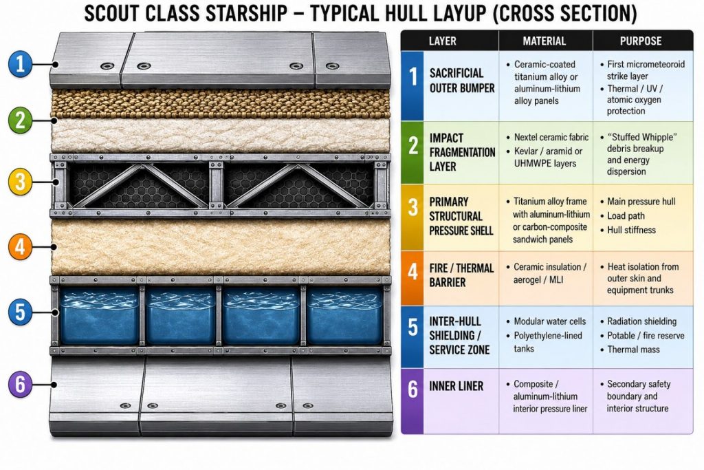
If a micrometeoroid strike penetrates the outer hull but not the pressure liner, the inter-hull zone becomes the sacrificial containment layer.
Fire Control System (FCS)
The fire detection and suppression system or fire control system is designed to extinguish any form of a fire hazard aboard the spacecraft. The system includes the following components:
- Fire Detection – Detection of smoke
- Fire Isolation – The location of fire(s)
- Fire Suppression – The means to extinguish fires
- Post Fire Atmosphere Restoration – The means to recover from fires
In microgravity, there is no natural air convection. To detect smoke, the smoke Photoelectric Smoke Detectors are mounted inside ventilation pathways (See FDS Components Locations). Based on smoke particles scattering a light beam, light from a laser source is reflected by mirrors back to a photodiode (obscuration).
Scattered light is measured by a second photodiode (scattering). Other components include Ventilation and Air Monitoring/Supply Systems, FCS Component Location and Status
Fire Containment Zones
The FCS Main Portal displays the location, intensity, local schematics, worst case scenarios, proposed responses, and additional detailed information regarding a fire.
Fire Suppression
Fire suppression recommendations are displayed on the FCS Main Portal and consider location, scope, fire intensity, localized payload, equipment integration, and proposed responses. Both FCS Automatic and Manual Response are included.
Manual Response
Portable Fire Extinguishers (PFE) direction of approach.
- Suppression Port Portable Fire Extinguisher with Smoke Detector Portable Breathing Apparatus.
Automatic Response
Automatically initiated FCS functions:
- Fire Suppression Ports – Fire is suppressed by a combination of blowing the fire out
- Remove power to racks-to isolate ignition sources
- Isolate modules by shutting off ventilation inhibiting introduction of O2 and N2 into modules (inhibit pressure control assembly)
Post Fire – Atmosphere Restoration
Post Fire Atmosphere Restoration can be initiated manually or automatically. The system will only engage automatically when the fire is 100% extinguished. Gaseous Contaminants are removed by Atmospheric Restoration System (ARS). It Removes 19 different gaseous contaminants using a catalytic oxidizer (ambient) and expendable & regenerative charcoal beds. The Harmful Impurities Filter removes gaseous trace impurities (particles of 0.5 to 300µm to a level of 0.15 mg/m3) and the Trace Contaminant Control Subsystem (TCCS) removes gaseous contaminants using a catalytic oxidizer (400ºC) using expendable sorbent and charcoal beds. Sorbent contains LiOH which can remove acid gases.
Post Fire Air Quality Assessment is done with the following equipment: Compound-Specific Analyzer for Combustion Products (CSA-CP), Carbon Dioxide Monitoring Kit (CDMK), and final analysis using Draeger detector tubes for Atmospheric sampling, with GSC and AK-1 air sampling assemblies.
FCS Testing
A test of the Fire Control System is included on the pre-flight checklist and includes the following items:
- FCS Sensor Check
- Fire Suppression Testing and Enclosed Volume Tests (cylindrical nozzle)
- Post Fire Atmosphere Restoration and Air Check
- Atmospheric Quality Assessment
The existing fire-control concept should be integrated into damage control. The fire system already includes detection, isolation, suppression, and post-fire atmosphere restoration.
Damage control defines fire zones by compartment and include:
- Automatic ventilation shutdown
- Power isolation to affected racks
- Smoke extraction after suppression
- Trace contaminant cleanup
- Portable breathing apparatus lockers
- Fire suppression ports
- Manual fire stations
- Post-fire atmosphere testing
The system does not only extinguish fire; it also determines when the space is safe to re-enter.
Casualty Power and Data Routing
The ship already has isolated networks and an independent Emergency Net.
Damage control includes:
- Casualty power trunks
- Emergency lighting circuits
- Backup command terminals
- Portable data jacks
- Local control panels
- Emergency network repeaters
- Battery-backed compartment controllers
If the Command Net, Engineering Net, or Habitat Net fails, the Emergency Net should still support:
- Doors
- Airlocks
- ECLSS isolation
- Fire suppression
- Emergency communications
- Basic lighting
- Damage-control sensors
Structural Damage Control
The structural health monitoring system already tracks strain, vibration, thermal expansion, fatigue, crack propagation, and pylon alignment.
Damage control should convert that sensor data into action:
| Condition | Response |
|---|---|
| Minor strain anomaly | Log, monitor, restrict high-load maneuvers |
| Crack propagation | Isolate area, dispatch inspection drone |
| Pylon misalignment | Lock out warp initiation |
| Thrust-frame stress | Limit sublight acceleration |
| Hull deformation | Reduce pressure differential if safe |
| Ring-frame displacement | Suspend warp operations |
This is especially important because the warp rings and pylons impose structural, thermal, and electromagnetic loads.
Repair Assets
The Damage Control Center should control and inventory all repair assets:
- Hull patch kits
- Robotic patching tools
- Inspection drones
- Fire response kits
- Portable oxygen
- Portable lighting
- Portable power packs
- Emergency coolant bypass hoses
- Spare valve actuators
- Manual door tools
- Pressure curtain kits
- Sealant cartridges
- Replacement sensor modules
The Service Deck workshop and fabrication area should support emergency manufacture of non-critical replacement parts.
Emergency Operating Modes
The ship should have defined damage-control modes:
| Mode | Meaning |
|---|---|
| Condition Green | Normal operations |
| Condition Yellow | Abnormal condition; enhanced monitoring |
| Condition Orange | Active system failure; local isolation |
| Condition Red | Ship wide emergency |
| Condition Black | Loss of central control; local autonomous survival mode |
In Condition Black, local controllers should preserve pressure, fire safety, oxygen supply, and emergency lighting without requiring the AI, bridge, or main computers.
6.12. Thermal Management System (TMS)
The Scout Class uses a multi-loop thermal control architecture separating reactors, propulsion, warp-ring, and habitat cooling. High-temperature reactor heat is captured through liquid-metal primary loops and transferred to Brayton thermal recovery systems, storage banks. Propulsion heat is routed through independent aft thermal channels to stern radiator manifolds. Warp-ring heat is collected through pylon coolant trunks and rejected through dorsal and ventral aft radiators. Habitat and life-support heat are managed by a lower temperature distributed through Thermal cooling loops. Radiator systems operate at extremely high temperatures to maximize blackbody emission efficiency and reduce required radiator surface areas.
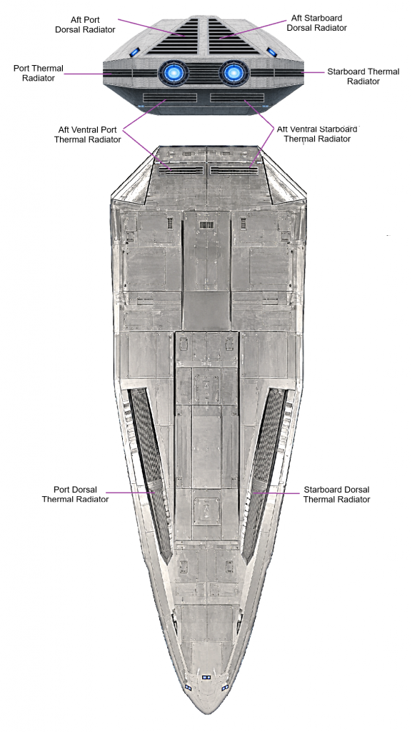
During high-power operations, deployable radiators extend from armored dorsal and ventral housing. In micrometeoroid or warp-transit conditions, the ship can temporarily store heat in phase-change thermal banks and water-shield thermal mass until radiators are available. Critical systems are protected by redundant pumps, isolation valves, coolant bypasses, thermal sensors, and automatic load-shedding controls.
Sublight engine thermal energy is dissipated through hull-integrated thermal channels to the radiators located above, below, and each side of the propulsion engines.
Excess FRC Direct Fusion Drive heat generation is dissipated from the radiators on the bottom hull of the vessel.
The thermal loops do not share coolant directly. They exchange heat through heat exchangers, so reactor faults or coolant contamination cannot propagate into crew systems.
| Thermal Loop | Handles | Location |
|---|---|---|
| Primary High-Temperature Loop | FRC reactors, Brayton recovery, power conversion | Engineering Deck / aft core |
| Propulsion Thermal Loop | Plasma/ion drives, magnetic nozzles, thrust chambers | Stern propulsion block |
| Low-Temperature Habitat Loop | cabins, bridge, avionics, galley, life support | all habitable decks |
Defensive & Situational Awareness System(DSA)
The Scout Class carries no offensive weapons. The DSA provides the situational awareness an exploration vessel requires to keep itself safe: contact detection and identification, hazard and debris tracking, threat assessment, evasive-maneuver coordination with the helm. Scout Class starships have no weapon defensive countermeasures. Where an armed vessel would prosecute a contact, the Scout Class characterizes it and, if necessary, avoids it. SCOUT Display logic is assessment-oriented: every contact is classified and assigned a hazard envelope, but the system offers no engagement controls.