The Scout Class moves between stars on a paired warp ring system, and within them on conventional sub-light engines. This chapter covers all four propulsion modes — warp, sublight, RCS, and fuel management — and the entry and exit sequences that get the ship to and from FTL.
Introduction
The Scout Class starship is designed around a layered propulsion architecture that allows the vessel to operate across three distinct flight regimes: precision maneuvering, high-efficiency sublight travel, and faster-than-light transit. Rather than relying on a single propulsion technology, the ship combines conventional attitude-control thrusters, fusion-powered main propulsion, and an external warp-field system into one integrated flight platform.
This arrangement gives the Scout Class the flexibility required of an independent exploration and survey vessel. It can maneuver safely near stations, orbital infrastructure, planetary bodies, debris fields, and other vessels; accelerate efficiently across interplanetary distances under fusion propulsion; and initiate long-range warp transit when mission profiles require travel beyond practical sublight limits.
The propulsion system is composed of four primary elements:
- Reaction Control System, used for docking, attitude control, station-keeping, low-speed translation, and fine maneuvering.
- Sublight Main Propulsion, provided by twin stern-mounted fusion-drive engines for high-efficiency real-space acceleration.
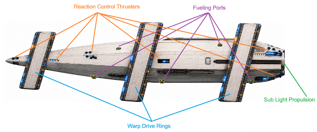
- Warp Propulsion System, generated through three external warp rings that shape and sustain the vessel’s faster-than-light field geometry.
- Propulsion Support Systems, including fusion fuel storage, power distribution, thermal rejection, inertial compensation, control logic, and safety interlocks.
The Scout Class propulsion architecture reflects the vessel’s exploration mandate. It is powerful enough to support extended autonomous missions, but it is not designed as a combat drive system. Propulsion authority is governed through S.C.O.U.T., the ship’s integrated operating and supervisory intelligence, which coordinates flight control, power allocation, navigation constraints, reactor output, thermal load, and safety envelopes across all propulsion modes.
During normal operations, the crew interacts with propulsion through the Pilot, Navigator, Engineering, and Defensive/Situational Awareness console roles. The Pilot controls maneuvering and helm execution. The Navigator develops routes, waypoints, transfer solutions, and warp-course planning. Engineering monitors reactor output, fuel state, thermal load, power routing, and drive readiness. Defensive/Situational Awareness tracks hazards and contacts that may require evasive maneuvering or course correction. S.C.O.U.T. continuously monitors these functions in parallel, providing recommendations, warnings, and procedural safeguards.
The system is intentionally redundant and fail-safe. Critical propulsion actions require authenticated crew authority, two-stage confirmation where appropriate, and local hardware interlocks that prevent unsafe operation regardless of software state. Main-engine burns, warp initiation, reactor mode changes, emergency shutdowns, and high-risk maneuvering commands cannot be executed solely by automation. The AI may recommend, calculate, prepare, and coordinate propulsion actions, but irreversible or mission-critical events require human authorization.
At the physical level, the ship’s propulsion design is built around a central hull with no nacelles or external engine pods. Sublight thrust is delivered through twin stern engines integrated into the aft hull structure. Fine maneuvering is provided by recessed RCS thrusters distributed around the bow, forward-midbody, and aft sections. Warp capability is provided by three external rings attached to the hull through structural struts, allowing the ship to generate the required field geometry without compromising the main pressure hull.
This propulsion concept allows the Scout Class to function as a believable, self-contained starship: agile at close range, efficient at sublight speeds, and capable of long-range interstellar mission profiles through warp transit. The following sections define each propulsion subsystem, its operating role, physical arrangement, fuel requirements, safety controls, and integration with the ship’s power, navigation, and command systems.
4.1 Super-Luminal Propulsion Drive
The Scout Class Starship uses an Alcubierre-type Hybrid warp engine utilizing a spacetime field generator that moves a localized region of space rather than accelerating the ship through space. The ship sits in a region of flat spacetime (no local acceleration felt).
- Spacetime contracts ahead of the bubble
- Spacetime expands behind the bubble
- The bubble itself translates through spacetime
- The ship never locally exceeds c (speed of light)
- But the effective displacement rate can exceed c
The practical interpretation is:
- Interior (crew volume): flat, inertial
- Bubble wall: extreme spacetime curvature (where energy is concentrated)
- Exterior: undisturbed space
As a warp field generator, its core functions are to generate a spacetime curvature field, maintain bubble stability, translate the bubble along the x-axis, and prevent collapse or asymmetry.

The Scout Class Starship uses three-warp ring architecture.
| Ring | Role |
|---|---|
| Forward ring | spacetime compression |
| Mid ring | field stabilization |
| Aft ring | spacetime expansion |
4.1.1 Warp Rings
Each warp ring contains warp expansion joints, independent superconducting coil cryocooling, emitter heat extraction, pylon coolant routing, and emergency quench protection. Ring heat is routed through the pylon trunks to dorsal and ventral aft radiator manifolds.
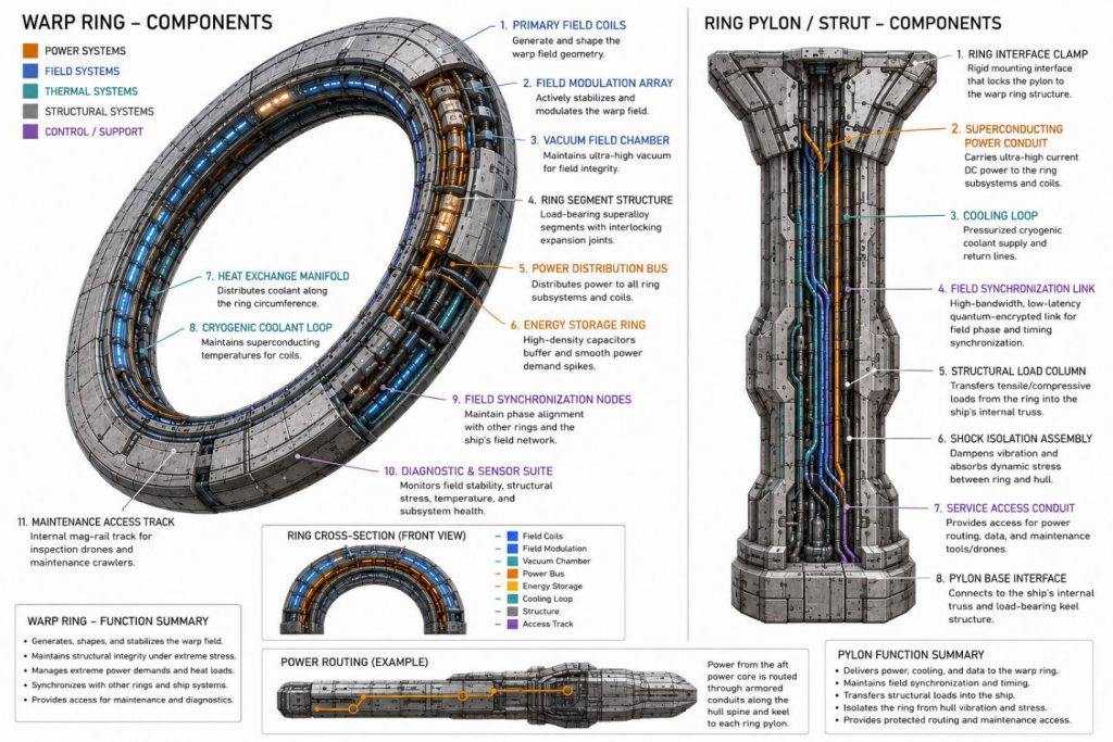
Warp rings have their own cooling architecture:
- superconducting coil cooling loop
- emitter thermal loop
- pylon coolant return loop
- field-stabilizer electronics cooling
- emergency ring quench dump path
4.1.2 Warp Ring Structural Pylons

Warp-ring pylons include active alignment actuators and dynamic damping systems to compensate for thermal expansion, field-induced vibration, and structural oscillation during warp-field transitions.
Each pylon contains:
- power feed
- coolant supply
- coolant return
- field synchronization cable
- structural load path
- active alignment actuators
- field-induced vibration compensation
- dynamic pylon damping
4.1.3 Warp Acceleration and Deceleration
4.1.3.1 Entry Sequence
Stage 0: Charge Field Capacitors
Stage 1: Ring Synchronization
- forward, mid, aft ring phase lock
- field coils ramp up
- bubble contour appears on engineering displays
Stage 2: Pre-Bubble Inflation
- local spacetime stress rises
- inertial compensation engages
- hull vibration increases
Stage 3: Bubble Closure
- habitable core isolates from normal spacetime gradient
- visual lensing appears
Stage 4: Translation Ramp
- bubble begins moving
- speed rises in bands, versus all at once
4.1.3.2 Exit Sequence
Stage 1: Translation Reduction
- bubble velocity reduced
- aft expansion field throttled down
Stage 2: Geometry Relaxation
- compression and expansion gradients flattened
Stage 3: Boundary Collapse
- bubble shell dissipates
- sub light systems regain full authority
Stage 4: Post-Transit Stabilization
- sensor recalibration
- ring thermal purge
- navigational fix update
4.1.4 Navigating at Warp
Navigation is accomplished by biasing ring output. Since the ship changes course by creating asymmetric curvature in the bubble, helm commands are requests for vector bias.
Example:
- stronger port forward-ring sector = slight starboard translation bias
- stronger aft lower sector = upward bubble pitch correction
- Therefore, helm commands are really requests for:
- vector bias
- field orientation
- bubble contour correction
4.3.4.1 Warp Ring Roles in Navigation
| Forward Warp Ring | sets destination corridor shapes leading curvature handles fine directional bias |
|---|---|
| Mid Warp Ring | preserves bubble symmetry damps oscillation keeps the ship centered |
| Aft Warp Ring | drives translation rate controls cruise intensity determines acceleration ramp |
Warp Ring and Ring Strut/Pylon Components
4.1.5 Control System
The dedicated Warp Engine consoles are in the Engineering Section and the Bridge. These are used to control the Forward Ring, Mid Stabilizer Ring, and Aft Expansion Ring. Engineering crew maintain ring synchronization through these consoles.
4.1.6 Hull Interaction
The hull sits inside the warp bubble; it does not interact with propulsion forces directly. Structural stress is mostly a result from field coupling, thermal loads, and electromagnetic effects.
4.2 Sub Light Propulsion
The sub light propulsion system handles everything the super-luminal propulsion drive cannot safely do:
- Departure and approach
- Orbital insertion / station keeping
- Fine maneuvering at interplanetary scale
- Emergency propulsion if warp is offline
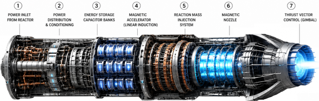
The Scout Class starship has two independent, high-power plasma drive modules integrated into a single stern propulsion block, capable of both efficient cruise and redundant maneuvering. They are Dual High-Power Plasma / Ion Hybrid Drives or, a magnetoplasmadynamic (MPD) accelerator hybrid design assisted by electrostatic ion acceleration. They accelerate plasma to extremely high exhaust velocity producing efficient thrust over long duration. The plasma is expelled through magnetic fields to shape exhaust.
They are the Port Main Drive and the Starboard Main Drive and are mounted symmetrically at the stern inside the 20 m × 10 m propulsion block. Each drive occupies roughly 6–8 m width and are separated by the structural spine.
Each propulsion unit consists of a power feed interface which draws from the main reactor bus buffered through capacitor banks that handle transient loads.
Thrust vector control is achieved via variable magnetic field shaping and differential thrust between port/starboard drives.
4.2.1 Performance characteristics
| Parameter | Value |
|---|---|
| Exhaust velocity | 50–200 km/s |
| Thrust per engine | 0.5–5 MN |
| Specific impulse | 5,000–20,000 s |
| Power consumption | 50–500 MW per engine |
4.2.1.1 Redundancy model:
| Normal Operation | Both Engines Active Balanced Thrust Straight Acceleration |
|---|---|
| Failure Mode | One Engine Offline Remaining Engine Compensates Reduced Thrust RCS Assist for alignment |
4.3 Reaction Control System (RCS)
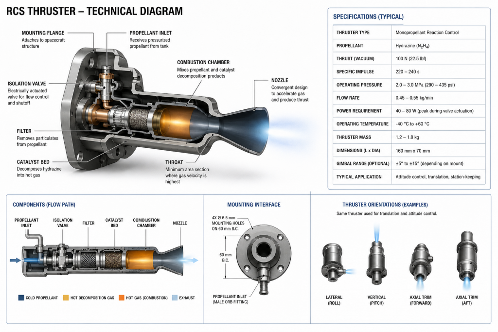
The Scout Class starship has a network of Reaction Control System (RCS) maneuvering thrusters used to control the spacecraft’s position, fine control, rotation, and translation. The RCS system is arranged in three control zones. Together they control
- +X / -X = forward / reverse trim
- +Y / -Y = port / starboard translation
- +Z / -Z = up / down translation
- Pitch
- Yaw
- Roll
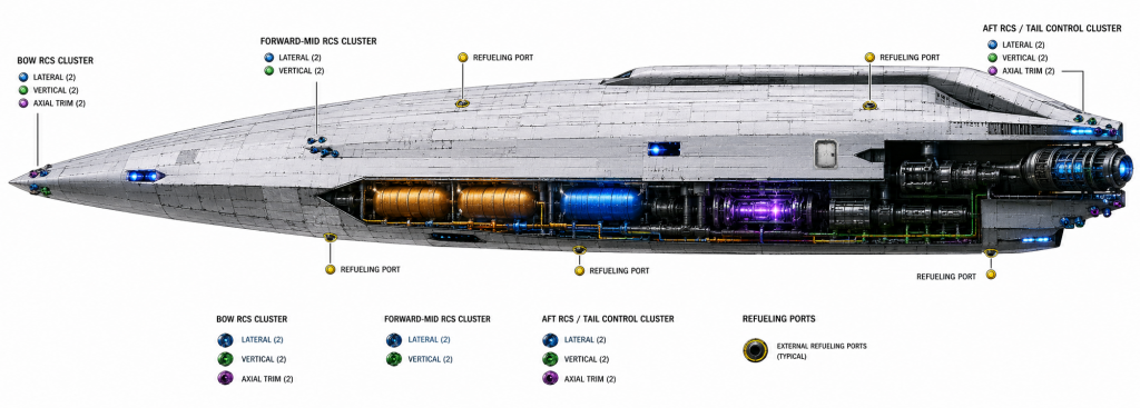
| The Bow RCS Cluster | The Bow RCS Cluster | The Bow RCS Cluster |
|---|---|---|
| Thruster Count | Location/Function | |
| Lateral Thrusters | 2 | Port Starboard |
| Vertical Thrusters | 2 | Dorsal Ventral |
| Axial Trim Thrusters | 2 | aft-facing thrusters for forward translation trimming / station-keeping balance |
| Forward-Mid RCS Cluster | Forward-Mid RCS Cluster | Forward-Mid RCS Cluster |
| Lateral Thrusters | 2 | Port Starboard |
| Vertical Thrusters | 2 | Dorsal Ventral |
| Aft RCS / Tail Control Cluster | Aft RCS / Tail Control Cluster | Aft RCS / Tail Control Cluster |
| Lateral Thrusters | 2 | Port Starboard |
| Vertical Thrusters | 2 | Dorsal Ventral |
| Axial Trim Thrusters | 2 | forward-facing jets for braking / reverse trim support |
Fuel
30 metric tons of D-He3 fuel: 12 t deuterium + 18 t helium-3 are stored in armored aft-midship cryogenic tanks feeding twin compact FRC fusion reactors. This includes Reserve tanks split port/starboard for redundancy.
| Normal cruise / ship power | 5 t |
| Sublight propulsion | 10 t |
| Warp-field power generation | 8 t |
| Emergency reserve | 5 t |
| Unusable margin / boiloff / handling reserve | 2 t |
| Total | 30 t |
Fuel Capacity
| Tank Type | Qty | Internal Size | Installed Envelope | Location |
|---|---|---|---|---|
| He-3 | 4 | 4 m Dia x 6 m long | 5.5 m Dia x 7.5 m long | 2 tanks port side 2 tanks starboard side |
| Deuterium | 2 | 3 m Dia x 5.5 m long | 4.5 m Dia x 7 m long | 1 port centerline-adjacent 1 starboard centerline-adjacent |
4.4.1 Fuel Balancing
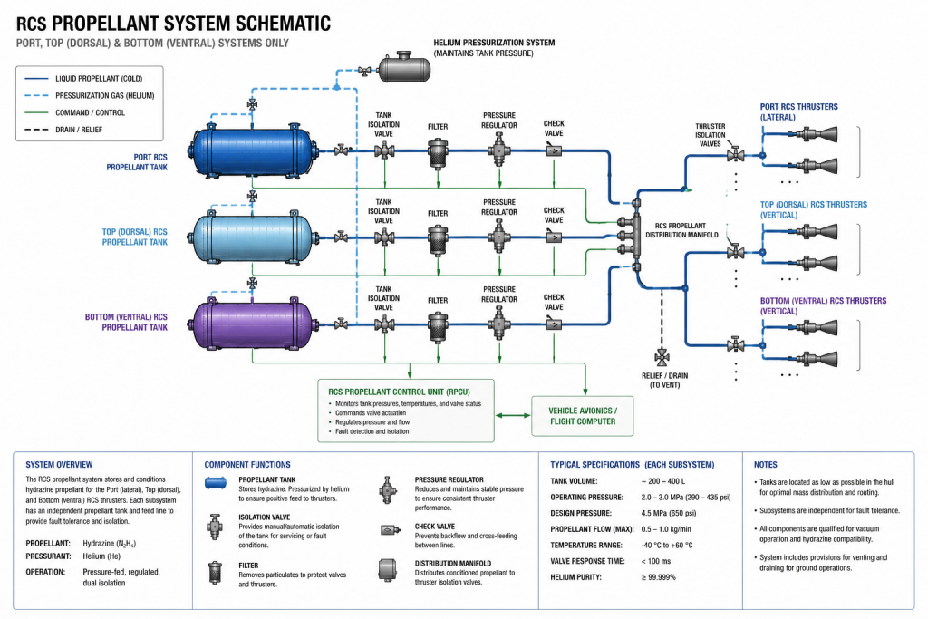
Fusion fuel and RCS propellant tanks are paired and symmetrically distributed within the starship. Fuel management prevents aft-heavy departure conditions, bow-heavy return conditions, port/starboard imbalance, and excessive vertical CG rise as lower tanks are depleted.
The ship computer continuously calculate the ships center of gravity using:
- tank-level data
- fuel mass data
- water distribution data
- cargo/supply loading data
- structural sensor data
- maintenance configuration data
Any CG excursion outside limits shall trigger:
- advisory alert
- automatic ballast correction
- engineering review
- propulsion/warp lockout if unresolved Power Distribution
Refer to the Fluid Management System for more information.
4.4.2 Propulsion Fuel Replenishment
Because the Scout Class has two completely different fuel systems, the ship has Hydrazine RCS servicing ports and Cryogenic D-He3 fusion fueling interfaces. These are physically separated for safety.
Dual port/starboard hydrazine servicing panels are recessed into the aft hull shoulders near the RCS propellant manifolds away from the airlocks and from the fusion fueling hardware.
The D-He3 fusion fueling ports are near the reactor fuel tanks and located on the dorsal centerline with segmented retracting doors. A cryogenic fusion fueling collar is integrated into the aft engineering spine.
Each service port is accessible for maintenance from inside the vessel and use orbital propellant umbilicals for refueling.